The rc_core_debug module parameter for the rc-core modules is gone. Debug must be enabled via dynamic debug.
Minor Fixes
There are minor fixes to ir-spi transmit and meson-ir timeout handling.
iMON
There is a new driver for the iMON Station, which is an external usb device (unlike most of the other iMON gear). It is a raw IR device, so it does no decoding in hardware.
The second new iMON feature is a decoder for the iMON PAD remotes. These remotes have their own protocol, which is decoded by the iMON Inside, iMON VFD or iMON Knob. I spent a fair amount of time decoding it, and I think this is the first time someone has figured out how it works. ir-keytable has be updated for this feature, which is not done yet. In the mean time, you can use it so:
Any mceusb device should have a wideband receiver for learning mode, which was not supported up until now. Learning mode should give you a more accurate reading, and can also measure the carrier. The downside is that the wideband receiver only works for short distances, so you have to hold your remote as close as possible to the IR receiver.
Using ir-ctl -m -r you can enable learning mode and carrier reports. The wideband receiver will remain enabled until you execute ir-ctl -M.
So you have your z8f0811 device from the ‘90s and you’ve misplaced the source code; what do you do? There is a simple method and a more complicated method if Read Protect was enabled during flash programming, using a Raspberry Pi as a flash programmer.
Using Debug PIN
The z8f0811 has debug pin, which controls the OCD interface (which has the descriptive name “On-Chip Debugger”. One of the commands is Read Program Memory (0BH). Since this is a one-pin interface, I connected an arduino and wrote the following program.
Then I connected my logic analyser to see what came back. It did send 0x2000 bytes – all of them are 0xff though! Turns out that the z8f0811 has a feature called Rom Protect (RP).
Bypass Possible?
While searching for a solution for this, I came across this Z8F04xx,08xx Errata, which says:
The Read Protect (RP) Option Bit does not prevent Flash access when bypassing the Flash Controller as described in ZiLOG Application Note AN0017 entitled Third Party Flash Programming Support of the Z8 Encore!® MCU. User code cannot be read through the On-Chip Debugger when read protect is enabled. User code can only be read out when bypassing the Flash Controller. Work-Around: None
The first hurdle was to remove the z8f0811 from the board. I tried using a regular soldering iron, and found it impossible. I ended up buying a hot air soldering station, which is much better.
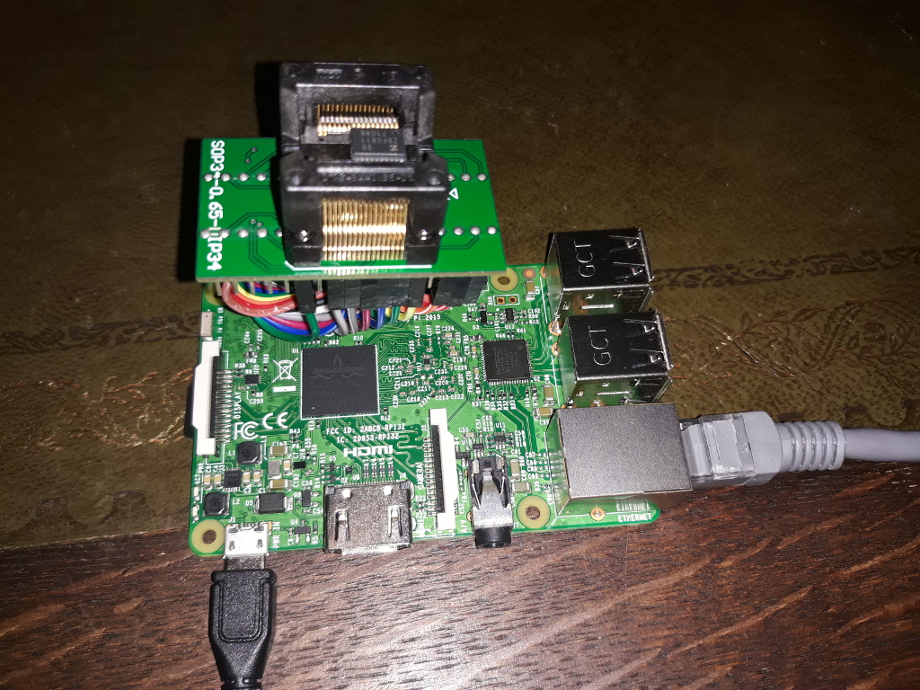
My arduino did not have enough gpio pins, and I suspected that it couldn’t generate a clock signal (PWM) either. So I used a Raspberry Pi for this.
According to the documentation, the lowest clock rate the z8f0811 supports is 32KHz. So on the Raspberry Pi I use pwm to generate that clock; then I connect that to Xin on the z8f0811, and also to another gpio pin on the Raspberry Pi so I can wait for the rising edge.
Most other pins need connecting: debug for setting flash bypass, reset for resetting the device after the pwm clock is set up, and all of port A, B, C pins (11 pins).
Implementation (software)
We’ll need to bit-bang various pins so even at 32KHz, we need to be very careful about being timely. The only way to do this in Linux is by writing a kernel driver, and holding a spinlock (to avoid interrupts).
This is built against kernel 4.13-rc4 (simply because I was using that kernel version for testing RC core changes on the Raspberry Pi, and I knew that that version worked). This is using Fedora 26 (armhf).
After booting the kernel, you can copy the flash memory using:
1
dd if=/dev/zdumper of=z8f0811.bin bs=8192 count=1
Finally
Presumably suspect the other z8f08xx and z8f04xx devices will work fine too; they need the same pins connected. I have not tested this.
I realise this device is a microcontroller and not a microprocessor, but I can’t help but dislike the instruction set. Why are there so many addressing modes for 4kb of ram/registers? The disassembly is painful to read and write, as the same register can be access in many different ways.
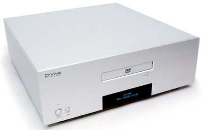
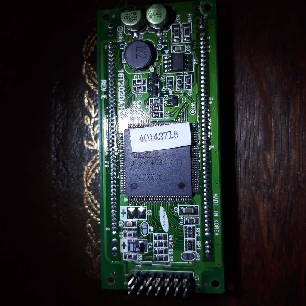
There used to be a driver for this device in drivers/staging/media/lirc/lirc_sasem.c, but that was removed in kernel v4.12. I’ve since found it on eBay, and here is the result of analysing it, and I’ve written a new driver.
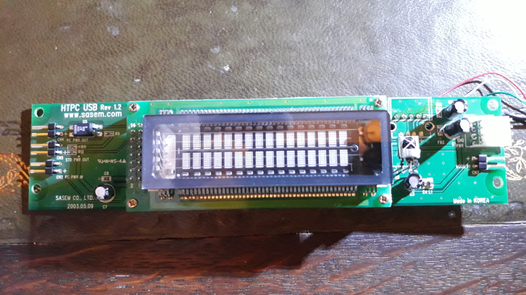
In the centre you can see the LCD, which is attached via a header. To the right you can see the IR receiver module. The LCD can be detached using the four screws. The LCD part is a NEC µPD16314 VFD (without a backlight). There is also a Cyruss CY7C63743 USB microcontroller. This drives the IR decoding and the LCD via its GPIO ports.
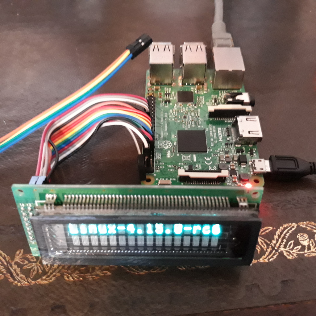
The NEC µPD16314 is a hd44780 compatible, which is ubiquitous and well documented. There is a driver for it in mainline, which can control it via gpio ports. So I tried to attach this LCD device to a Raspberry Pi via its gpio ports. This is easy to do with female-female jumper cables. After some measuring and experimenting, I got it to work.
The pinout of the LCD header is:
Ground
VCC - 5v not 3.3v
Not Connected (the pin is removed)
RS
R/W (not needed, connect to ground)
E
Bit 0
Bit 1
Bit 2
Bit 3
Bit 4
Bit 5
Bit 6
Bit 7
Now, after compiling a kernel for the raspberry pi with CONFIG_HD44780 enabled, and the following added to the device tree:
So that worked! Using the CHARLCD driver, you can set a cursor position, cursor blinking, and reprogram character generator data. The original lirc_sasem driver could not do any of that!
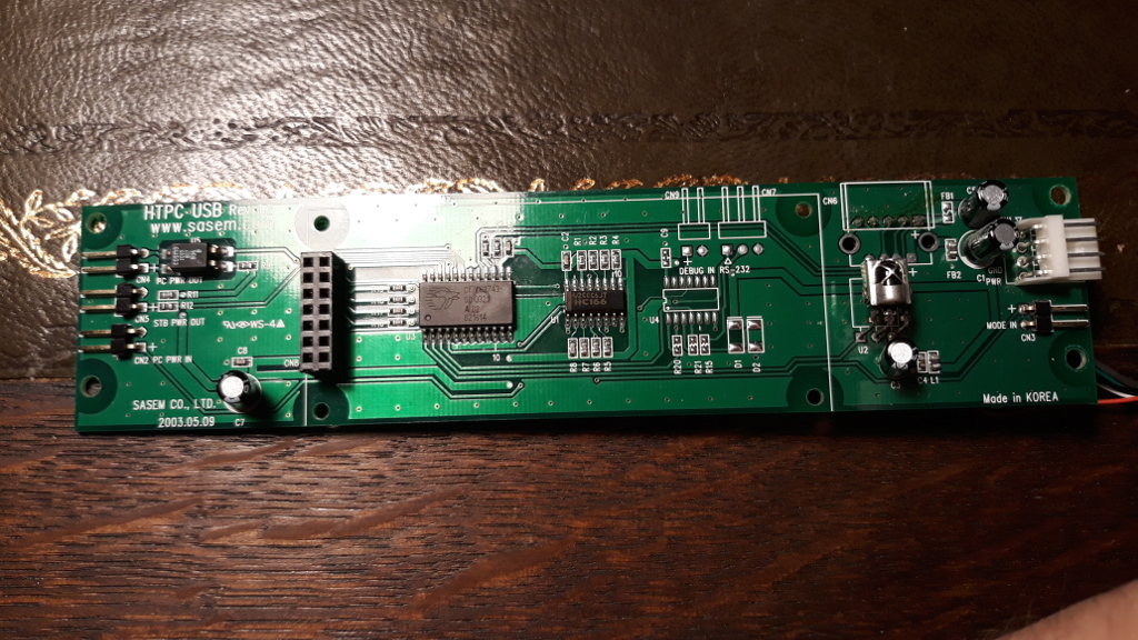
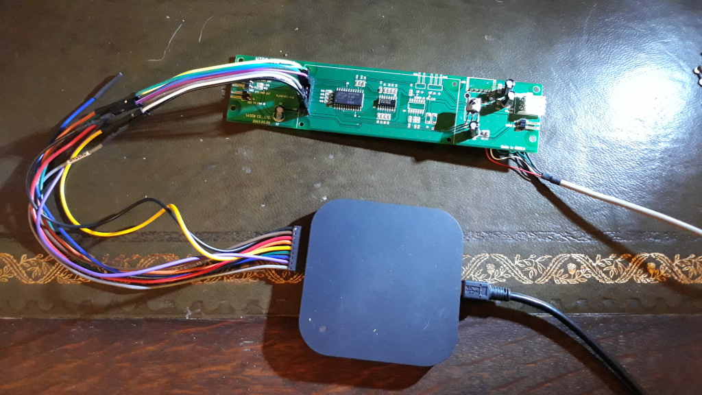
Now that I know the pins of the LCD header, I can try to figure out what the Sasem Remote Controller sends it, and how that relates to usb packets we can send to it from the driver. The CY7C63743 is a OTP (One Time Program) device. It’s a device which makes it very easy to create keyboards, input devices, anything which is a low bandwidth usb device. Unfortunately I could find no way of dumping its program memory.
So, instead I attached a Saleae Logic 16 logic analyser to the board to see what commands it sends. I quickly discovered that it’s actually using the 4-bit interface, even though all 8 bits are connected via the header. Also, when the device powers on, it sends a few write reg commands and “Welcome DIGN Home Theatre PC”. During this period it drops any commands it receives over usb. In order to decode the commands, I wrote a simple libsigrokdecode decoder called sasem.
Since the CY7C63743 has 16 gpio ports, I don’t know why 4-bit mode is used. 1 gpio port is need for IR receive, one for the power button, and presumably another for switching the motherboard on (in case power on was pressed on the remote). That still leaves 13 gpio ports, and the LCD needs just 10 (8 bits data, Enable and Register Select).
The LCD has two commands: write data and write register. If you want to reprogram the display characters, you first do write register to DDRAM (display data) to set the location, followed by the letters you want using write data. When you attempt this via usb, it sends an extra “Write register DDRAM” before each data byte, which increases every time (from 0x80 to 0x8f for the first line and then 0xc0 to 0xcf for the second line). This makes it impossible to write to character generator ram (for your own characters), since every write data it sends a superfluous set DDRAM write register. I have no idea why this was done!
In addition, if you want to write to a register, you write 0x07 followed by the register value to usb. This means it is impossible to write 0x07 to the display. However this is one of the custom characters, for which we can’t write the graphics ram anyway.
The other oddity is if you do a write register DDRAM (to the location), then that command is passed on the device. However, as soon as you write data to the device, it gets preceeded by an annoying extra “write reg DDRAM” with an different address! So, the usb microcontroller maintains its own display position address, which you can modify using 0x09 0xYX (Y=0x4 for top, 0x0 for bottom) and X can be 0x1 to 0x10 (not base 0).
As for the Infrared interface, using ir-ctl I tried sending every protocol, and it reports data for NEC, Sanyo and JVC protocols. For some reason the JVC and Sanyo protocols comes out as semi-garbage, so the new driver only supports NEC.
Armed with this knowledge, I’ve created a new driver drivers/media/rc/sasem_ir.c. The driver can do a lot more than the original driver (e.g. cursor, blink) but no character graphics. Alas.
The iMon SoundGraph has very similar hardware, and I’ll be looking at that soon. I only have one model, if anyone can help with getting access to some more, that would be great.
rc-core supports a fair amount of devices, but not all are supported well. If there is any IR hardware which does not work, please send it to me and I will fix linux support if at all possible. I can send it back once the work is complete, else I can add it my collection of IR hardware.
iMon SoundGraph
The iMon SoundGraph support is fine, but some particular devices are not well supported. I’m sure the early iMon Knob most likely does not work; and judging by various posts there are others which don’t work either. Having access to those devices would be very helpful.
SIR
The SIR driver was ported from lirc without having hardware to test it on. It would be great if it could be verified it actually worked. I think the early Thinkpad T60 (like the Core Solo models) had a SIR IR port.
Remotes (IR protocol support)
Any remote which can send (or receive!) rc-mm, xmp, grundig, bang & olufsen protocol would be very interesting. I could use that to write IR decoders and encoders.
In kernel v4.16 there are more changes than usual for rc-core.
lirc_zilog
First of all, the last remaining staging lirc driver has been ported to rc-core: lirc_zilog. The old driver needed a “signal database”, a file with specific IR messages in it. So to make it work, you needed a file haup-ir-blaster.bin and lirc_zilog.conf and then needed to know the specific name of the IR message you wanted to send.
The new driver is in ir-i2c-kbd.c. The transmitter now works like other IR devices, in that it can send raw IR (i.e. just pulse and space). The old signal database files haup-ir-blaster.bin and lirc_zilog.conf are no longer needed and not supported either.
This driver is for the Hauppauge PVR-150, HVR-1600, USB PVR2 and HD-PVR IR interface.
End of lirc staging and lirc_dev.h
With lirc_zilog gone, the entire staging lirc directory is gone, and the lirc kernel api is gone too. This means that no out of tree lirc drivers will compile any more.
Just to be clear, this makes no difference to userspace.
This means that lirc_rpi no longer works. For the Raspbery Pi, there is the gpio-ir-recv, gpio-ir-tx (or pwm-ir-tx) to replace this driver. Those drivers are generic and much shorter than lirc_rpi.
Not having the lirc kernel api made it possible to clean up much of the kernel code. The lirc userspace api (see lirc_dev.c) is much cleaner than what we used to have (lirc_dev.c and ir-lirc-decoder.c).
Lirc scancode interface
One feature I have been working towards for some time is the new lirc scancode interface. This makes it possible to do two new things.
First of all, we’ve had in-kernel IR encoders for some time. They were only used for the nuvoton wakeup IR programming. Now, it is possible to send IR by specifying the protocol and the scancode required. There is no need for keymaps or anything complicated.
fd = open("/dev/lirc0", O_RDWR); if (fd == -1) { printf("Failed to open /dev/lirc\n"); return-1; } mode = LIRC_MODE_SCANCODE; if (ioctl(fd, LIRC_SET_SEND_MODE, &mode)) { printf("kernel too old or device cannot send scancodes\n"); return-1; } if (write(fd, &sc, sizeof(sc)) < 0) { printf("invalid scancode or failed to transmit\n"); return-1; } close(fd); return0; }
Secondly, rather than transmitting scancodes, it is also possible to receive scancodes with complete protocol information. This is really useful for use-case of “what protocol is my remote using?”.
Both features can be used using v4l-utils from git, or v1.14 when it is released. To find out what IR protocol your remote is using, you can use ir-keytable -t. Ensure you have all protocols enabled (-p all) and (-c) to safe-guard from any scancode mapping to e.g. power-off.
1
2
3
4
5
6
7
8
9
10
$ ir-keytable -c -p all -t
Old keytable cleared
Protocols changed to lirc rc-5 rc-5-sz jvc sony nec sanyo mce_kbd rc-6 sharp xmp
Testing events. Please, press CTRL-C to abort.
2124.576099: lirc protocol(rc5): scancode = 0x1e11
2124.576143: event type EV_MSC(0x04): scancode = 0x1e11
2124.576143: event type EV_SYN(0x00).
2125.601002: lirc protocol(rc6_mce): scancode = 0x800f0410
2125.601051: event type EV_MSC(0x04): scancode = 0x800f0410
2125.601051: event type EV_SYN(0x00).
Note the rc5 and rc6_mce protocol names. This is two different remotes, a Hauppauge rc-5 remote and Microsoft MCE remote. Again, This requires a recent v4l-utils.
Opening /dev/lirc more than once
If you happen to run the lirc daemon, then the /dev/lirc device was always in use since the lirc daemon would hold it open. This is no longer a problem, now a /dev/lirc device can be opened as many times as needed, and every process that opens it will get a copy of the IR received. This actually saves some memory if no process has a /dev/lirc device open, as there are no buffers allocated (they are per-fd now).
www.mess.org used to host the multi emulator super system website, however that project merged with MAME back in 2015. The old website can be seen here.
Since the domain is no longer important to the project, I’ve reclaimed it for my own purposes: that of the maintainership of rc-core in the linux kernel.